Garrattfan's Modelrailroading Pages
Fairlie Merddin Emrys
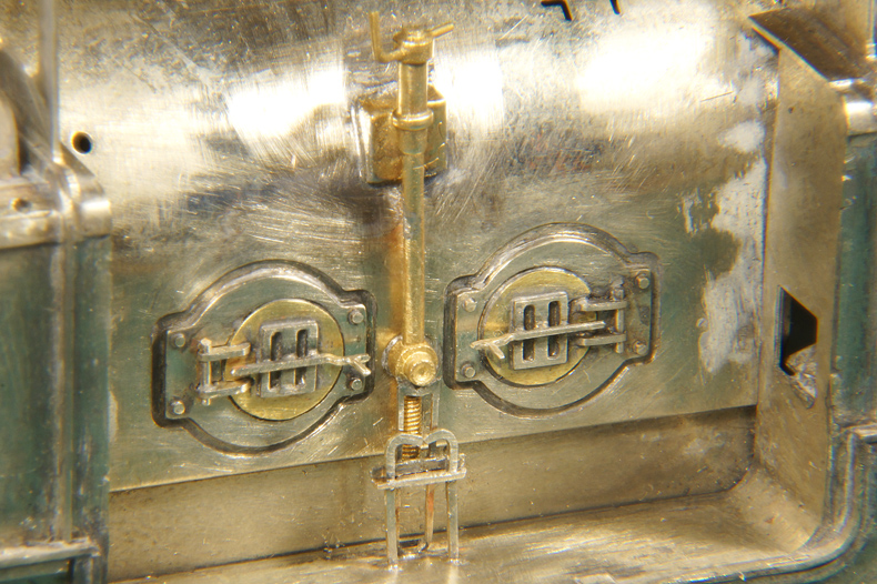
7.2 Detailing: cab fireman's side
Firebox doors |
|
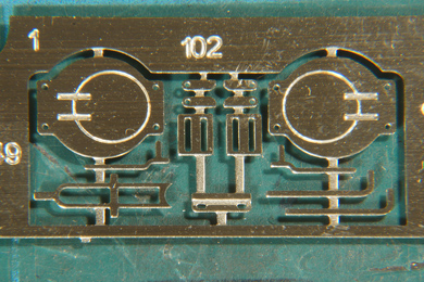 |
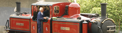
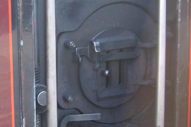
Photo from the manual DVD used with kind permission of Paul Martin ©2013 EDM Models |
The firebox doors and their accesories are contained in one group on the etch [232-237]. At close range it becomes visible that the doors themselves are not represented on the etch. In reality there is a plate that is bolted in the firebox hole and the firebox door is mounted on that plate. Well on the etch the plate was there but the door was represented merely by an etched recessed ring. I didn't like it. |
|
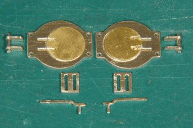 |
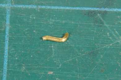
So while prepping the part I cut two doors from 0.2 mm brass sheet. I sawed two slots where the hinges would come. |
 |
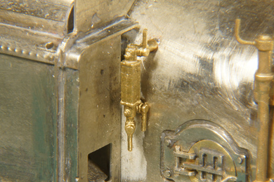
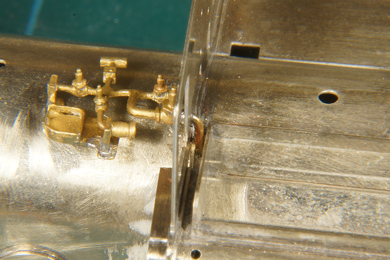
The firebox door backplates are soldered using the pin method leaving the four ends out to simulate the bolts. |
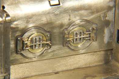 |
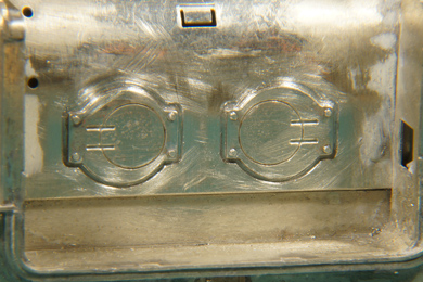
Completed firedoors. The added brass door will now appear as a slightly raised cover giving a better impression from the real doors. |
Locomotive brake |
|
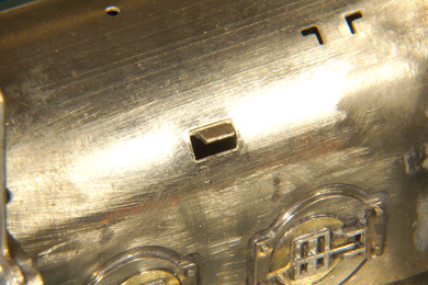 |
Construction of the brake starts with folding out the etched tab in the firebox |
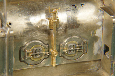 |
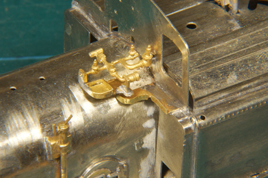
I tack soldered the round part of the spindle between the firebox doors first, then worked my way around the triangular top end and then returned to the bottom end for final soldering. In hindsight I better coud have soldered the door handle flat. I could have made the curl in the hinge as per the original. But what's done is done. Who will notice?
I also soldered the handbrake spindle into place [238] |
Final parts added [239]. They stub end on the floor. The real loco has holes of course, but there is a limit to what you can model, even in a relatively large scale as O. |
|
 |
The water gauges [240] seem different on the sprue but they are identical, just facing two ways. Keep the spigots to the sprue as long as you possibly can. |
 |
The pipes connecting the water gauge are very thick and need a considerable amount of filing to fit in the holes. I did not ream the holes because the holes are already oversize as they are. The top hole needs a pass of a drill of same size to let the top pipe pass exactly level. The water gauge is soldered from the inside of the firebox, which reduces the need to clean up. |
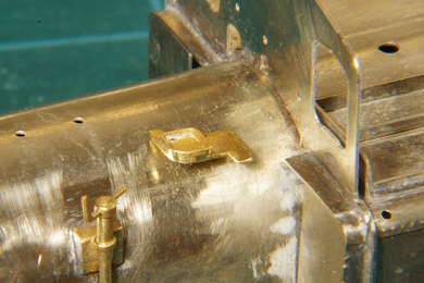 |
Getting this bracket in place was no easy task [242]. It should fit in the L-shaped holes but it wasn't all that easy. The L-shaped legs of the bracket need a good deal of cleaning and filing, taking care not to overdo it. The casting had a convenient notch that should keep the bracket in the correct height but this caused me so much trouble that I filed it away on both legs and simply positioned by eye before tack soldering one leg from the inside |
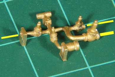 |
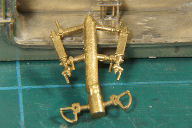
Then I worked on the pipe casting [243, 265]. As supplied it has three pipes.
So after much fitting and trying I cut the remaning two pipes off and drilled three holes of 0.5, 0.5 and 1.0 mm respectively. Then I fitted until I found the right height of the bracket, requiring loosing the tack solder only once, and then I gave the bracket a final soldering and... |
 |
...soldered the piping on the bracket |
 |
A new 1.0 mm pipe, bent to fit, and ready to be fitted from the outside... |
 |
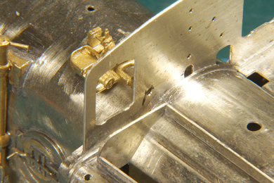
... like so. The bracket, by the way, does not entirely show up on the prototype photos. The L-shaped legs and the support the piping can be found but the small "table" between them is not present in the real loco. I decided not to bother about it and leave it as supplied. |
 |
An unknown part is added. I have no idea what to call it, but on the photos of the real loco it is used to put stuff on. |

Sign my
GuestBook